The decision at stake
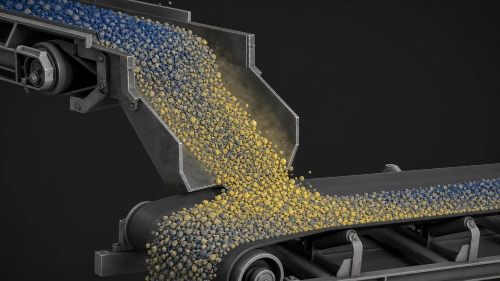
The CV-04 loading point spilled fines every shift, with the cleaning cost and the risk that come with it. There were two chute proposals on the table and no way to choose between them without building one.
Geometry and mesh
DEM uses no volume mesh: geometry enters as a surface and what gets defined is the size distribution and the particle population. The chute, the skirt and the first two metres of the receiving conveyor were modelled.
Physics and assumptions
Hertz-Mindlin contact with cohesion, calibrated with site material. Calibration ran against three tests: angle of repose, sliding angle on steel and box discharge. Fine particles were grouped to keep the run viable; that grouping is declared and it bounds the conclusion.
Convergence
Time step verified against the Rayleigh criterion, and mass balance checked to hold throughout the run.
Validation
The simulated flow was compared against video of the real operation at the loading point: the stream trajectory and the spillage zone match what was observed.
Conclusion and limits
The chute with a retention curtain was chosen, with an estimated spillage reduction of 38 t/h. That estimate depends on the material moisture measured during calibration: with wetter material cohesion rises and the result changes.